Design Problem
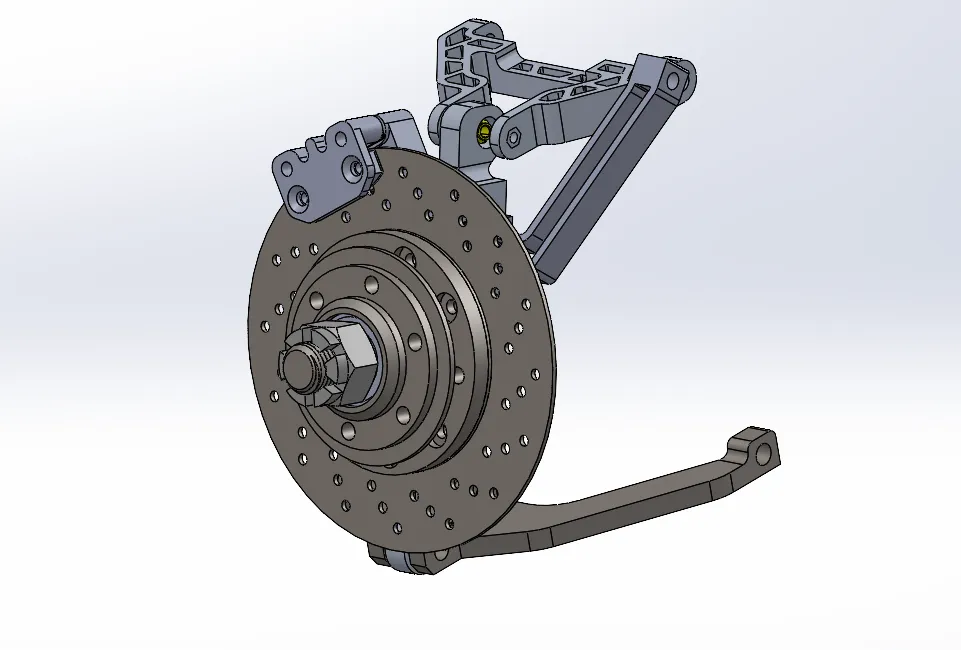
The existing front brake rotor interfered with the vehicle’s upright. Since modifying the upright could affect the surrounding suspension geometry, the rotor was redesigned to fit the existing front suspension while remaining compatible with the hub and braking system.
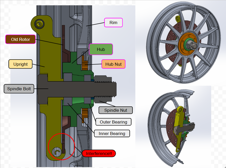
Figure 1. Original rotor-to-upright interference.
Rotor Redesign
I redesigned the rotor in SolidWorks using AISI 4130 steel, with the main goals of eliminating the interference, reducing mass, and simplifying manufacturing.
The previous rotor weighed 1522 g. The redesigned rotor weighs 845 g, and the required spacer weighs 153 g, bringing the redesigned assembly to 998 g. This reduces the total mass by approximately 34%.
The old rotor used a stepped, non-flat geometry. The redesigned rotor is a flat 3.18 mm plate, allowing it to be waterjet-cut directly from flat stock. This avoids the additional machining required by the previous geometry and reduces manufacturing complexity and cost.
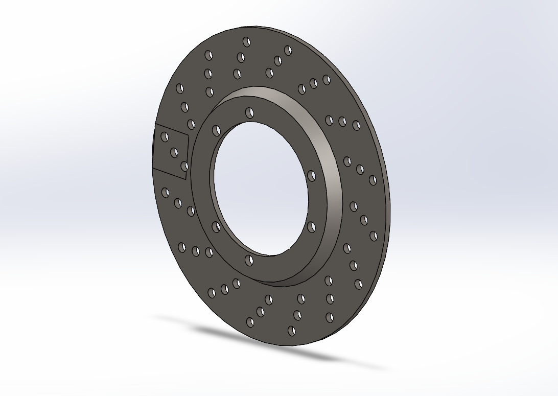
Figure 2. Previous rotor with stepped geometry.
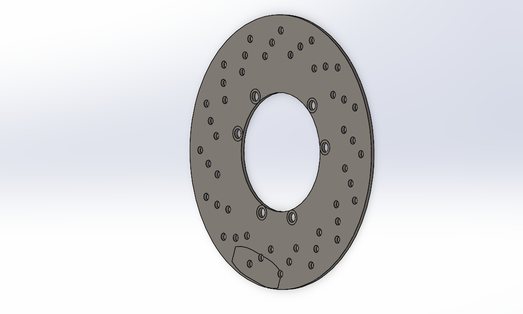
Figure 3. Redesigned flat rotor.
Design for Assembly
Since the new rotor is flat, I designed a spacer to position it correctly relative to the hub and brake caliper. The spacer sets the rotor’s axial position and helps centre the braking surface between the brake pads.
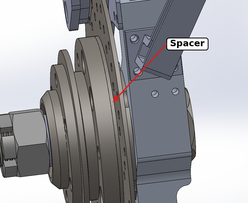
Figure 4. Spacer positioning the rotor relative to the hub.
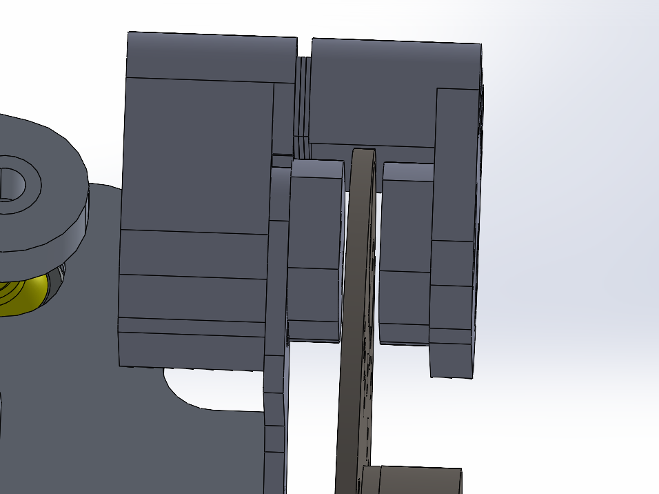
Figure 5. Rotor centred between the brake pads.
Assembly Integration
The redesigned rotor and spacer were integrated into the existing front suspension assembly in SolidWorks. The side views show the geometry before and after the redesign and confirm that the rotor clears the upright.
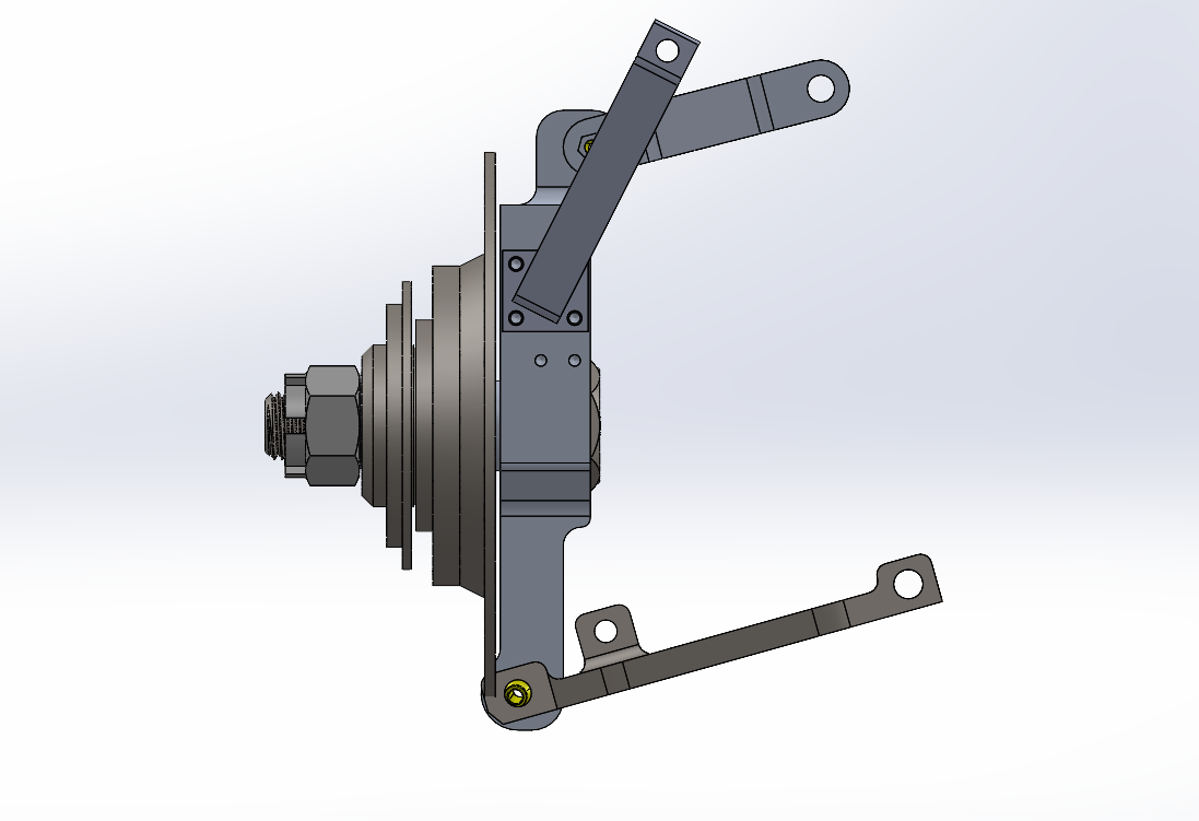
Figure 6. Previous rotor assembly.
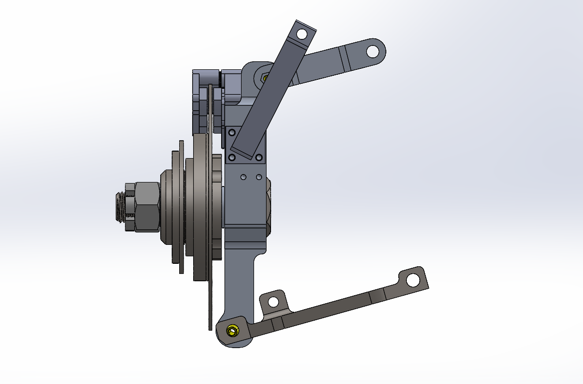
Figure 7. Redesigned assembly with upright clearance.
Engineering Drawing
I produced an engineering drawing for the redesigned rotor with the required material, dimensions, hole patterns, tolerances, and geometric controls for manufacturing.
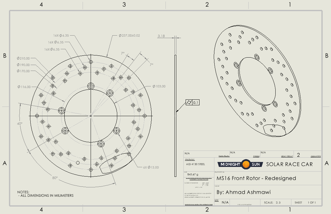
Figure 8. Engineering drawing for the redesigned rotor.
Results
- Reduced total assembly weight by approximately 34%.
- Reduced manufacturing complexity and cost.
- Eliminated the original rotor-to-upright interference.
- Improved assembly by using a spacer to correctly position the rotor.
- Centred the rotor between the brake pads for proper braking alignment.
- Produced a manufacturing-ready engineering drawing with GD&T.